Building My UGEARS Model U-9 Grand Prix Car
The 21st June was Fathers Day in the UK and a present received from our daughter was this lovely construction Kit from UGEARS.
The rest of this story is about the journey I went on while building it.
The model was completed on 6th July following quite a few 'learning by doing 'problems along the way.
I did not record how long it took or how many parts there are to complete the model.
I was amazed, however, how many moving parts the build involves and considering that the instructions say that no glue is needed, I did need to glue two joints on my engine.
The neatly packaged box contains multiple sheets of three ply wood onto which each of the parts has been finely Laser Cut making their access very simple to achieve.
One very soon gets used to the smell of scorched wood which permeates the room where the model is built.
The package also contains a bag containing two sizes of Elastic Band, a pack of Non Standard Toothpicks / Cocktail Sticks, a small sheet of Sandpaper, a small stick of Candle Wax and a 51 page Instruction Booklet.
The Candle Wax is used to lubricate the sides of all moving parts and the teeth of every gear wheel in the kit.
I learned from following a YouTube video that this is not totally successful and that Graphite from a soft pencil lead, or grease is a better option. I eventually needed to use both.
There are a number of interesting and helpful video's there
I was warned, by someone who has already built and other UGEARS model of a Morgan Car, that there are just enough of these sticks required to complete the model.
However, I found that by using the waste cuttings where practical I still have quite a few unused sticks left over.
The Wide Elastic Bands are used for the Drive Unit and the Wheel Tyres and the Narrow Bands are used for the Front Suspension and one for the Left Side Gear Wheel drive.
The sheet of Sand Paper is used to carefully sand off the little burrs of wood left on each part where the Laser Cutting joins need to be carefully broken to gain access to each part.
The accompanying Instruction Booklet is superb with very detailed diagrams of each part.
There are various Safety Instructions to be read before starting and, as one who did not do this, it is well worth studying every page before starting, even if they may not appear understandable until actually building each part.
Had I done this I would have found that one of the parts is actually a 'Start / Stop' sliding part and understood why my engine appeared to be locked.
Building the Engine.
Reading the first construction page requires 4 parts to be taken from one of the sheets.
It also shows how the Toothpicks are to be used to join four parts together.
I found that the Sticks were slightly too large to push into the holes here so I found a twist drill bit of the same size and used it to ream out any holes which were so tight that the sticks would break while trying to push them through.
My Drill Bit in situ and the Pointed Nose Pliers used to carefully turn the drill.
There are 4 individual plates making up each Block. What I did not realise until much later in the build is that both blocks have to be assembled identically and not mirrored as I had.
This mistake caused a rebuild of one block when I realised that there was no offset for the two rows of 'V8' form Pistons
More Reaming.
This part is the Camshaft for the Valves. Here I am giving it a liberal coating of Candle wax.
These parts are the 16 Valve Cam Followers.
My two Mirrored Engine Blocks before the rebuild.
The lack of Bore Offset is clear to see.
The Cam Followers waxed and placed on the Camshaft.
This page is all about creating the Pistons and building the Crankshaft.
The Crankshaft with the Connecting Rods built from two parts each.
The Crankshaft parts ready for lubricating.
Assembling each Connecting Rod before pressing out the 8 Pistons
The completed Crankshaft ready for me to discover that it would not fit the incorrect Engine Block
The Crankshaft showing the Piston offset.
The Engine Assembly Diagram.
The two correctly built Blocks, Camshaft, Crankshaft and End Plates.
The two items at the top of the page are Tools provided in the kit. One for cutting the correct lengths of Toothpick and one for fitting the Tyres on the Wheels later in the build.
Frequent disassembling of these parts caused the Joints here to loosen so I chose to Glue them using wood glue.
Here I am making the valves from specifically cut to length sticks and two sizes of Valve Discs which again are a tight push fit..
There are 16 in total - 8 of each size.
Here are all of the valves in place. The base of each rod is a push fit into a slot in those pear shaped Cam Followers shown earlier.
The Valve Fitting diagrams.
Here is the diagram for construction one of the two Elastic Drive units.
I consider building these parts to be the most difficult part of the build, particularly with my semi arthritic thumbs needed to fit the wide elastic into the tiny slots in each of the wooden discs.
Stretching and prodding was necessary to get these ends ito their slots so that each double row of elastic is the same length.
The Drive units have to fit into these large holes in the end plates.
Two end pegs have to inserted into the end plates before fitting. The diagram shows this fitting in two stages but it is easier to fit both at the same time.
This photo shows the completed fitting but belies the difficulty I encountered to fit them.
After fitting the two drive cogs onto the right hand end, each elasticated barrel has to be stretched across to reach the other side and be held in place until the left side gear wheel and Peg is fitted.
Maybe it would be easier to assemble with two sets of hands.
I mentioned earlier needing to glue the end plate joints. it was this assembly that just kept pulling the end plates inwards due to the high tension on the elastic.
Once disassembled and glued the problem was solved.
With the Engine mostly built we are assembling the floor base plate here.
At this stage I did not realise that it was the steering mechanism that I was assembling.
Once the steering gears are fitted then the engine is slotted into the base plate.
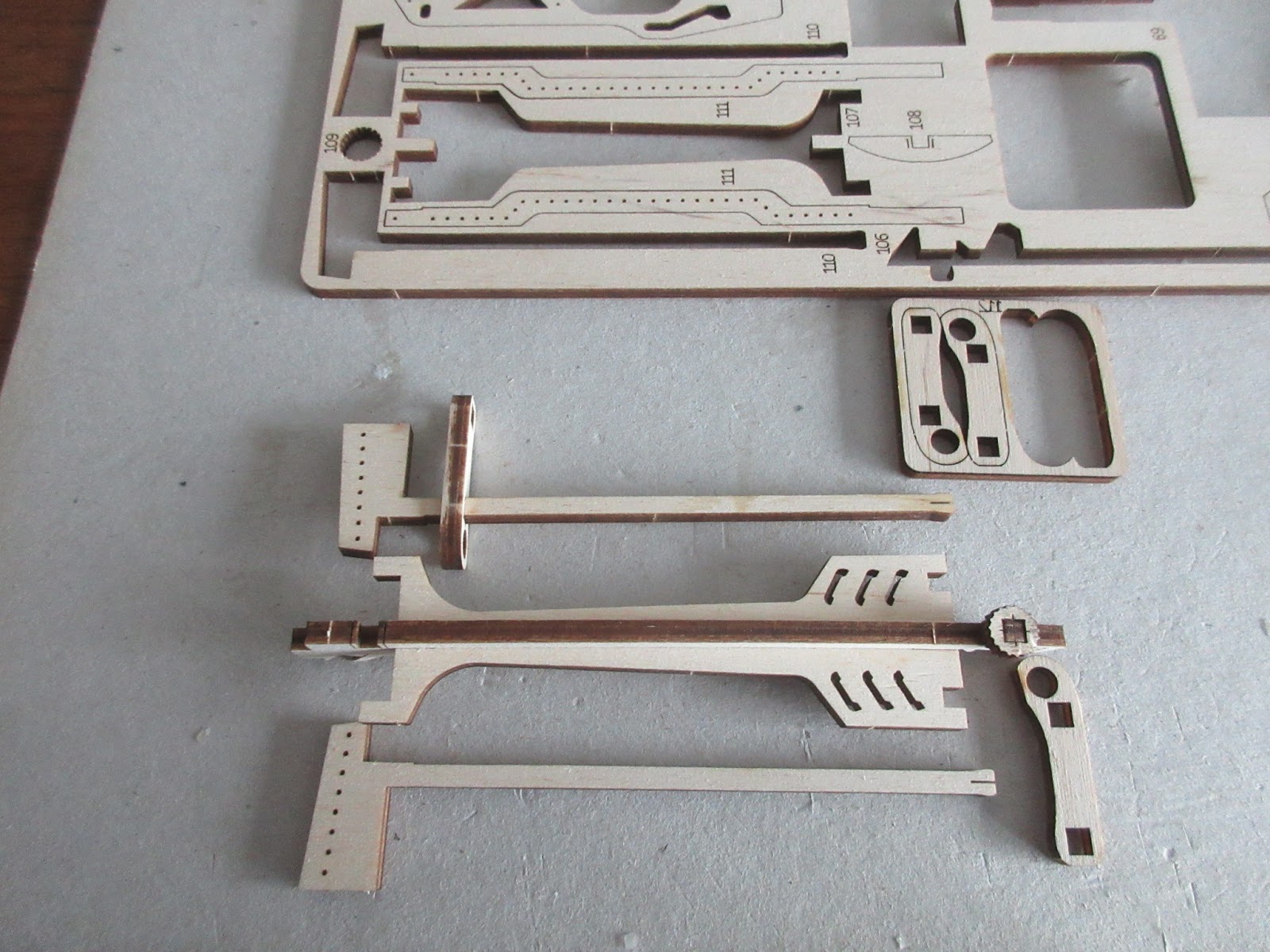
The parts on this plate are used to build the rear drive shaft and the body sides.
The drive to the rear axle is quite complex and this large gear wheel is part of that drive system.
The three parts in the lower right make up the drive shaft which is held together by 4 disc collars.
Here is the assembled Rear drive shaft made up of 4 parts held in place by 4 disc collars.
At the right hand end is a transfer gear and a hexagonal disc, the use of which I did not understand at this point in the build and its effect would cause me to half dismantle to find how it worked and why it was jamming the drive mechanism preventing shaft rotation.
A second problem with this shaft, I was to find out later in the build, is that for some reason, it was 4mm too long between the font and the rear gear wheels preventing me from fitting the rear and front plates into the side plates.
Eventually I was forced to shorten the gear wheel limiting parts of the shaft by 4mm to allow it to spin freely once fully assembled.
I did notice that little spring lever on the lower edge of the interim plate and the fact that it fitted into one of two square holes in the floor.
I did not realise what the plate was for as a result of not reading to the end of the Instruction Book.
It turns out that it is the Start Stop sliding switch and without some modification that little spring would not slide out of the square holes.
A little sanding of the spring lug and the creation of a 'ramp' out of the square hole and the problem was fixed.
The hexagonal disc on the drive shaft fits into the half hexagon in the plate preventing the shaft form turning while the elastic drives are being wound.
Simple, once you realise!
Next the steering wheel and dashboard are assembled with 3 gear wheels carrying the wheel motion down to the steering rack. Lubrication of the gear wheel sides is important.
Quite a few moving parts but easy to assemble.
Next, the side plates have to be prepared with the first of 4 gear wheels which are used to operate the Forward / Reverse mechanism added later.
The prepared sides.
Another tricky part to build is the Drivers Chair. The superb laser cutting has been utilised to create a bendable Chair Back.
It has to be carefully curved and then slotted into the base plate where it locks itself.
It would be very easy to split open the chair back so much care must be taken.
Fitting the side plates requires careful handling as there are lots of location points to bring together.
Once the second side is attached it is not possible to access any of the moving parts without a dismantle.
Having more problems with the small cog on the drive shaft not engaging with the large horizontal cog I am about to undertake my second dismantle and may resort to gluing that small cog to the end of the drive shaft to ensure constant meshing.
When I see others models running well and mine does not run then determination takes over.
With the dismantling now in progress I discovered the problem immediately. The end of the drive shaft carrying the rear gear wheel had sheared off. Disaster.
My gluing decision has now gone up a notch.
Out into the garage a find the smallest Panel Pin, Cut off its head.
Then drill a matching hole in each broken part so that I could insert the pin, and re assemble the parts adding a liberal coating of Araldite along the way.
The Glued Parts
I took the opportunity to add glue to the other end as this could be another weak spot.
Now to leave it overnight allowing the Araldite to set hard.
Having re assembled the body once more I will proceed.
At this point the Engine and Drive Shaft are spinning well again following the regulation 6 turns of the winder.
I decided to continue to the end of the build.
Ready to progress to the Front End
These parts form the Radiator Fan and the first two parts of the Winding Mechanism.
With the Fan & Winding Ratchet Cog fitted the grill is ready to go on.
However, Later in the build I knew that the tension on the wound elastic was really tight and putting tension onto the rear gear sets.
After just a few wind ups the toothpick peg on this left hand gear actually split allowing the cog to disengage with the winder cog.
Back to the build. Here is the completed Radiator.
The Fan seen from the Engine Bay
Here are the parts needed to assemble the see through Bonnets.
Part Constructed.
The completed Bonnet.
The two parts forming the Dashboard.
The Dashboard location.
The completed Dashboard.
Adding the Side Strengtheners.
The Side Strengtheners and Bonnets fitted.
Preparing to fit the Rear Axle.
The Axle is made up of two parts held together with Gear Cogs and Spacers.
The fitted Axle.
This diagram shows the many parts forming a complex combination of Gear Cogs and a Carriage which operates the Forward and Reverse Gears using a Side Lever
Here we can see the right side sliding gear shifting plate and the operating lever.
This diagram shows the parts linking the right and left side gear carrying frames.
The base tabs of the two side frames ready to receive the base frame.
The Base Frame fitted and pegged in place.
This board, and the one below, shows the two Axle Parts now missing and the Rear Wheel & Spare Wheel Parts ready for assembly.
Each Wheel is made up of 4 layers. Here the first two are pegged together.
Fitting the third and fourth layers.
Adding the Elastic Band Tyres.
Adding the Wheels to the Rear Axle.
The three completed wheels ready for fitting.
Pegging the Axle Ends.
The Fitted Wheels.
Fitting the Spare Wheel.
The Fitted Spare Wheel with its removeable securing Peg.
Next the two Front Wheels are constructed similarly to the Rear Wheels but with different Hub parts.
Before fitting the wheels, the Front Axle is fitted using the two thin elastic bands doubled and threaded through the Axle and hooked onto the Hangers creating a suspension effect.
The Axle with its pivot greased ready to have the elastic bands doubled through their slots.
After the first pass the bands are given a single twist and passed through the slot again
Here is the completed suspension with the crossed elastic on just one pass.
The elastics cross over looks like this, below.
The Front Wheels ready to fit.
One disc each side of the Wheel and a Peg fitted in the axle.
The fitted Front Wheel.
Creating the Exhaust Manifolds is quite fiddly
First the Exhaust part has to be split to allow each Header to slide into position.
Next the two parts of the Exhaust have to be fiddled back into their original position to allow the wavy peg part to be slid into place locking the Headers in position.
This operation required a little lubrication to allow the peg to slide in easily.
The completed manifold fitted into its two locating holes in the side panel.
I am not sure what this toothed wheel part would have been called or what its function would have been.
It is a simple construction popping the pegs into place.
The parts under construction.
The completed wheel fitted into the side panel and driven from the rear axle using the third fine elastic band.
Assembly of the Winding Crank Arm.
There are four parts plus four toothpick pegs involved.
The completed Winding Crank
The Crank slots into the socket in the radiator where it meshes with the small peg in the winding sprocket. 6 x 180 degree turns are recommended to wind the elastic.
The Crank resides in a slot next to the drivers seat when not in use.
The sliding Stop/Start lever must be in the stop or Parking position for winding the elastic.
The lever on the right side can be set into forward or reverse drives.
Once the car build is completed there is just the Trophy left to make.
Trophy Construction Diagram
Once more the parts are quite precision cut and tight to assemble but the result is quite satisfying.
The Post Mortem
Having had to partially dismantle and repair parts of the car three times now, it has still not run.
Despite parts working well on their own, frustration has taken over. The build was quite enjoyable otherwise.
The completed model now just sits and graces my bookcase.
Frank