The Neck of the guitar needs to be firmly fixed to the body and the current vogue is to use a 4 bolt fixing plate which I would source on line along with other essential hardware.
This particular fixing plate seemed the best available despite being branded for a 'Fender' or 'Franks' Guitar.
I also purchased these special screw nuts to ensure that the neck would eventually be tightly secured to the body.
This being the 5th amateurish Guitar I would build, I decided that rather than produce a less than perfect finger board.
I would purchase one already finished complete with its frets in place and finished.
This 21 fret version is modeled on the 'Fender' styling and therefore suitable to being bolted onto the Driftwood Body, provided I could recess it the correct depth and angle.
The Tensioning Key holes are also perfectly formed ready for me to fit my set of keys.
The set of middle of the road tensioning keys complete with screws and ferrules.
Before I could set about trying to form my driftwood body I had a few more decisions to make based on the space available on the surface.

There is definitely not enough room for this much equipment.

Something like this more simple organisation may fit the limited space.
No room for a Tremolo Bridge either.
I found this unit on the internet with its two Humbucker style pick ups and a cluster of control switches, independent tone knobs, a volume control and cable socket.
I would need to cut this carrier plate into smaller sections to suit the space available.
I would need to keep the area carrying the two pick ups together and cut a separate area carrying the controls with its backing surface.
With the lack of space available, I chose to purchase a 'Tune-O-Matic' Bridge set to fit close to the rear pick up.
I also like the look of the Roller Bridge.
The Tune-O-Matic on a Gibson Les Paul Guitar.
The last of the current hardware pieces are these tiny String Tensioners.
These will be located between the String Tensioning Keys at the Top 'Nut' to ensure that strings cannot be dragged out of their grooves.
They are only used for the thinner D,G,B &E strings so I will only use two of them.
I have been scratching around for a source of the small countersunk and raised head screws for use in securing the two perspex pieces to the front of the body.
Then these turned up on the internet so another job done.
And now a new set of strings. Always a minefield for me as I have no idea how the different numbers are selected.
I chose fender this time but they could have been from any electric guitar brand
I still need to order the Chrome Pegs used to attach a shoulder strap and to order a strap as well.
The next stage involved considerable head scratching and doodling while trying to decide how to progress with the body of the guitar.
I though it best to strip the White Perspex of all the components and set them to one side until needed again.
Unsure of the whole plan I decided to cut away just the area that will carry the Adjustable Height Pickups and shape the front edge to fit the taper of the wood block..
Having traced their location from the perspex sheet, I now needed to form the pick up holes in the wood.
Not owning a Router I set about to drill a line of holes around the perimeter to the correct depth.
It was at this point that I would discover the difficulty of working with multiple layers of plywood.
My chisels, while sharp, tended to bounce rather than cut.
As can be seen at the lower left, the wood could not take working with narrow borders without breaking away.
I would need to come back to work them more later to ensure the correct fit when both pickups were
remounted on the perspex.
With pick up locations set I now needed to commit to the location of the controls.
These knobs and switches would need to fit around the location of the two parts of the Tune-O-Matic Bridge even though the fixing studs for these would be located and fitted once the neck position was located and cut.
Here is the eventual shape of the Perspex marked on the wood along with the position of each controller.
There is not enough room to keep each of the controls in there original position on the perspex.
However, they would all need to be retained within an area covered by the silver grounding sheet adhered to the reverse of the perspex.
The method would once again be boring holes and joining them together with cutting and chiseling until the required depth and space for cables was created.
The deeper I cut more of the top edge was breaking away.
I would need a plan to disguise this with wood filler at the end.
And there in the centre hole at the top, I would meet my nemesis.
A blind Wood Screw positioned before the top layer of plywood was added.
It would take ages to clear the wood from around it before I could get a screwdriver to its head, only for it to snap off at the base of the hole.
Before completing the locating hole in the wood, I cut the perspex carrier to shape and located each of the controls so that they are all well within the silver area.
This is how they will appear on the finished guitar.
After much fitting and re fitting, a couple of slots cut to take the cables, re soldering of a broken wire, both pieces now fit in their correct locations.
This piece needs some thought into how to make it look smarter.
Both Perspex pieces have to now be stripped again to receive edge and corner shaping and their protective covers need to be eventually stripped.
The next stage is preparing the body to receive the neck and fingerboard unit.
I need to drill 4 holes in the neck which align perfectly with the holes in the Body and the polished Fixing Plate.
Dropping the backing plate into the neck locating recess I am able to mark the location of the 4 hole centers.
Because of the stresses which will be applied to this Neck Joint, when the strings are tightened, each component of the joint will need to be ultra tight.
With my low skills and basic equipment, I know that drilling tight holes which all line up when opened to their correct size, is not going to be easy.
These bolts are too tight at the moment so the holes will need opening very slightly later.
Here the bolts are test fitted into the base plate and so far the holes all line up.
You could say that this was the easy part.
The difficulty comes next when I have to get the threaded fixings set into the neck so that they line up exactly when the neck is set tight into its recess.
The Neck had been clamped in place at the moment I transfer drilled the pilot holes through those drilled in the Base.
I have test fitted the 4 fasteners which will eventually be tightly screwed into the base of the nicely polished neck.
The bolts are too long so will need to be shortened so I'll get on with that job.
You could say that I could drill deeper holes in the neck but with only 1inch of total depth available that would be too risky.
The challenge now is to hand drill holes for the fasteners which are both centrally located and vertical so that the bolts meet the holes exactly.
Here is a copy of the fitting diagram and options for necks of different depth.
I copied this from the fixings advertisement.
I ordered the longest bolts in the thicker 5m size, which I needed to cut down, because at the time I was unaware of the depth my neck would be.

This is the first hole drilled 8.5mm and slightly countersunk.
Without the use of a Tower Drill, I just hope that they will all be 'vertical'.
The wood of the neck is very dense and it took a while to drill to the required depth, 3mm deeper than needed.
The small Pilot Holes locating the other three positions are clear to see.
Having been supplied with one extra fixing, I was able to make a test fixing in an off cut of wood and it worked very well, particularly when it came to screwing the fixing into the wood.

The threaded metal fixing is slightly tapered so that it should go in vertically as it is screwed into its hole.
A Hexagonal Rod Tool is supplied to enable the screwing in process.
Here the fixing is half way home but the density of the wood is making it very difficult.
The benefit will be that it will not come loose throughout the life of the joint.
Note! The ebony piece covers a channel where a tightened metal 'tensioning rod' is recessed into the neck to prevent any 'bowing of the neck when the strings are tightened.

The countersinking allows the fixing to be fully recessed so that the joint will not be compromised by any protruding metal.

A second fixing being screwed in diagonally opposite the first fixing.
Using my Power Drill to enter the fixing but even that was not powerful enough to complete each one.
The Bolts are now ready for the neck to undergo a test fitting.
It is getting there.
With the neck test fitted I am now able to use my long metal ruler to extend mark each side of the neck to the location for the bridges.
This way I can center both parts and hopefully the strings, when fitted, will sit over the frets correctly.
The finished appearance is gradually evolving.
While the Neck is out of its protective cover I may as well fit the Tuning Keys.
Fortunately these were supplied with all parts needed intact.
Once all of the keys are connected, Lightly secured and aligned, a small hole is drilled to take the small chromed wood screw which will prevent them ever turning when their threaded sleeves are fully tightened.
Each Key is a tight Push Fit into their ready prepared locating holes.
For the upper side a threaded sleeve with integral hexagonal fastening nut head and polished washer is provided.
Once the Wood Screws are tightly secured then the Hexagonal Head on the front side can also be tightened down to fully secure each key.
I need to make a final decision for the finish of the body.
More blobs of wood filler are needed to fill where some rotten wood broke away during shaping.
I have ordered a Lacquer Clear Coat to spray the final coats but it is what will go over the rough wood.
I am considering using an area of this Beach Surface photo to cover the back and maybe the front.
If not I may purchase a special guitar print from hundreds of designs produced for this purpose.
As can be clearly seen here, there is so much wood filler that the natural state of much of the wood has been lost.
Even sanding the complete areas was damaging some of the plywood layers effected by being in the sea for an unspecified length of time.
I thought of trying a few alternative treatments before settling on a final effect.
At this point I have to admit to having no experience on wood finishing techniques other than using propriety brands for treating such as garden furniture.
First a trial coat of basic dark oak wood stain which Not that good and I knew would not cover the wood filler.
Next I decided to try and stabilise the wood by giving it a soaking coat of Polyurethane Varnish.
The Varnish drying.
Following a severe sanding to remove as many rough areas, particularly around the edges I decided to try a coat of Guitar Spray Top Coat Lacquer purchased from a Guitar Parts Supplier.
I have used this lacquer before and unusually it dries with a White hue. At this stage I cant see this product producing a deep shine????
I contacted the supplier who reckons that the hue is caused because I am using it in a damp environment and that I should be applying it in a warm room.
As we don't have as warm spraying room I will revert to using my polyurethane varnish for its final coats.
When I found the lump of drift wood, the many layers of plywood were held together with Glue and Brass Countersunk Wood Screws and featured a Single Brass Loop attached to one edge using Two Small Dome Headed Brass Woodscrews.
Having cleaned and polished the screw heads I intend to refit them all as decorative features when the Guitar is finally assembled.
The next stage is to position the two parts of the bridge and to mark the locations for the 4 holes I need to drill, suitably sized to take the fixings.
I actually did this position marking initially while the neck was trail bolted to the body.
This was essential to ensure that each edge of the bridge is in line with each edge of the Fret Board.
Prior to starting my staining and spraying I drilled 4 small pilot holes in the centre where the Bridge Fixings would be placed.

Now that I have started the wood finishing process I have opened each hole to the correct size and depth to suit the parts which will be inserted into the Guitar Body.
Here, I have positioned the parts to be fitted.
The fixings for both Bridge Parts will need to be tightly 'press fitted' into the holes.
Fitting both these and the Pick Ups etc. will need to be a last operation once the the body has been completely coloured and spray finished.
Today brought another disappointment as I once again trial sprayed this special clear coat on the back of the body.
I sent this photo to the supplier as this is how it dried.
The spray can label states clear gloss and I have have is a foggy grey matt finish. Totally useless.
This is what a satin finish looks like and as this will only be visible along the edges I will finish it with my Polyurethane Varnish applied with a soft brush.
I will now cut and fit the sheets of my sea bed print and glue it to the front and back surfaces ready for varnishing.
It is supposed to be a Rustic Driftwood Guitar after all.
But before that I will prepare the perspexes ready for final fitting.
Now to drill and countersink some extra fixing holes and then finish the edges of the perspex panels. To do this easily I needed to dismantle the parts once more.
Bevelling the edges to expose the wafer line of black was best achieved using the angled blade of my Stanley Knife to 'drag scrape' the edges.
Before removing the protective film and re assembling I also need to drill some extra fixing holes in this panel.
They look quite messy at this stage but the two layers of protective film have been working well.
Here is the finished panel holding the pick ups reassembled with the protective film removed from both the Perspex and from the faces of the Pick Ups.

Another test fitting before applying the decorative surfaces.
To add to the Drift Wood authenticity I have decided to re insert two of the original Brass Wood Screws once the surface is finished.
Now to work on the Decorative Surfaces.
It goes to say that this is very much experimental.
I have printed my beach photo onto A3 size paper, trimmed it to shape and pasted it onto the rear of the body.
It does look a bit bland.
On the front I am using an A4 print version of the same photo.
Again it has been trimmed to size and pasted to the block covering all of the apertures.
Once dry I have opened up all of the recesses created to take the Pick-Ups and The Controls and the 4 hole to take the Tune-o-Matic bridge.
Next I decided to overspray the edges with the same black used to spray the edges.
It does not look that cleaver at the moment even though much of this face will be covered with the perspex and the bridge parts.
The light is not very good so the back looks even worse.
I will be giving the whole unit a coating of Polyurethane Varnish.
This may have the effect of diluting the black overspray but it will not be until the first coat is on and dry before I decide whether to stick with the finish or to take it all off and start again.
The Back with its original Brass Bracket reattached after three coats of Polyurethane.
The Front with two Token Brass Screws re inserted and ready for its parts to be fitted permanently.
The Edge Finish still showing signs of the Plywood layers. There is no plan to utilise the Brass Bracket on the finished guitar.
I have decided to go with this finish and its Sea Bed Trompe-l'oeil decoration as it is.
Just a reminder of how it looked before the overspray.
Now for the assembly and a plan to purchase a Mini Vox Amplifier and Cable ready to try it out. .
The First Job was to press home the 4 Tune o Matic Bridge Posts which have to fit so tightly in their pre drilled holes.
Having watched a video of the process I realised that I needed to fit a ground cable to be soldered onto one of the Tone Adjuster casings.
A small diagonal hole was drill to gain access and the Bridge End of the grounding cable was splayed and trapped when the post was pressed in.
Ideally, something like a Bearing Press was needed to push the post into the body but without one of those I used a combination of Padding, 'G' Clamp and my soft mallet to drive them home.
The initial measuring between the posts is critical and to say that I had created a 'Tight Fit' for the Strings Holder would be an understatement. However they are in.
The two smaller posts, which carry the Hight Adjustable Bridge went in smoothly.
One of the lateral adjustment grub screws can be seen and fortunately an Allen Key was provided for the purpose.
The completed fitting with just the ground cable to solder in place.
The Pick Ups are set in place next and the cables tucked into their slots provided.
The Ground Cable is ready for tinning and soldering to the base of the nearest 'T' Tone Knob Casing.
The 5 control units now have their securing nuts tightened and both of the white panels are in place and secured with their counter sunk screws.
The three Knobs are in place however If some 'smarter' versions appear these may be changed later.
The Neck was fitted next and the 'Action' checked with my ling ruler.
However, after fitting the strings and tightening them I realised that the Neck joint needed to be pressed home with my soft face 'G' Clamp and the Bolts tightened further. I will do this tomorrow and re tune.
Lastly I had two more fittings to attach.
1. The Shoulder Strap lugs.
2. The String Locators for the D, G, B & E strings.
The forward Shoulder Strap Lug.
The Neck Plate fitted - The F is for Frank
The String Tensioners.
The two String Locators are in place but were problematic in that the thin screws supplied with them kept snapping off flush with the neck meaning I could not get them out.
The nearest one has an alternative screw which will be temporary until I can source better ones.
So here it is fully assembled and just waiting for some fettling.
All I need is that Mini Vox and a Cable (with a 90 degrees plug at the guitar end.)
End of journey from that old piece of Driftwood of unknow use or origin.
Thank You for following - Frank.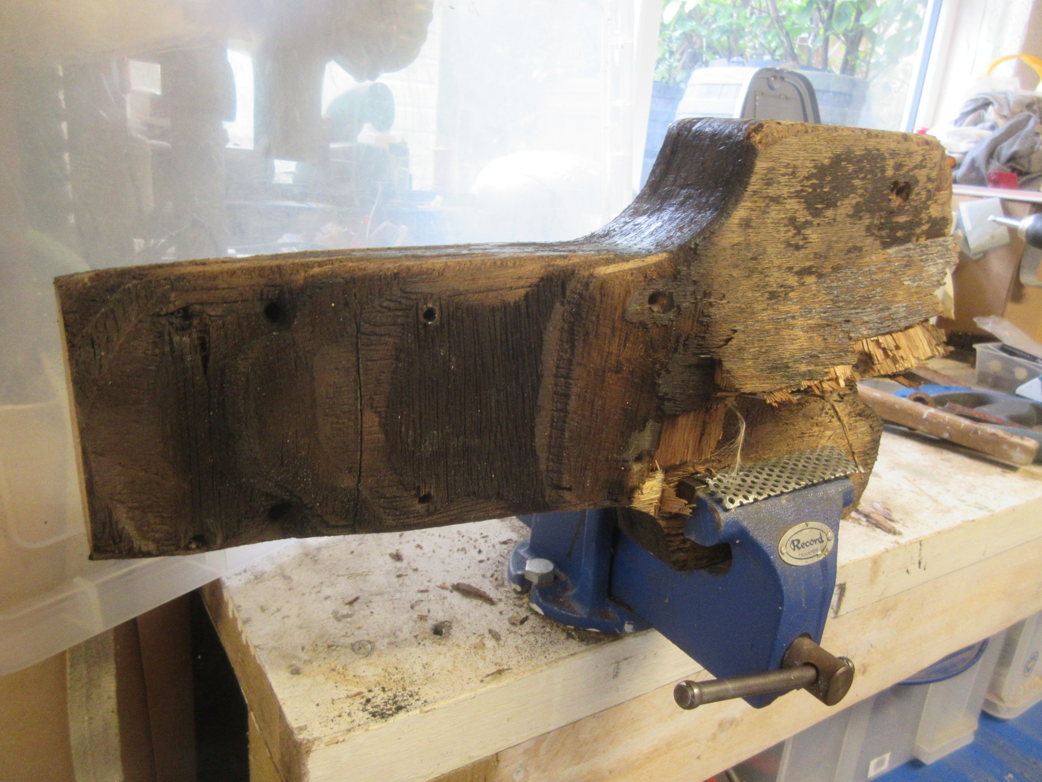


No comments:
Post a Comment