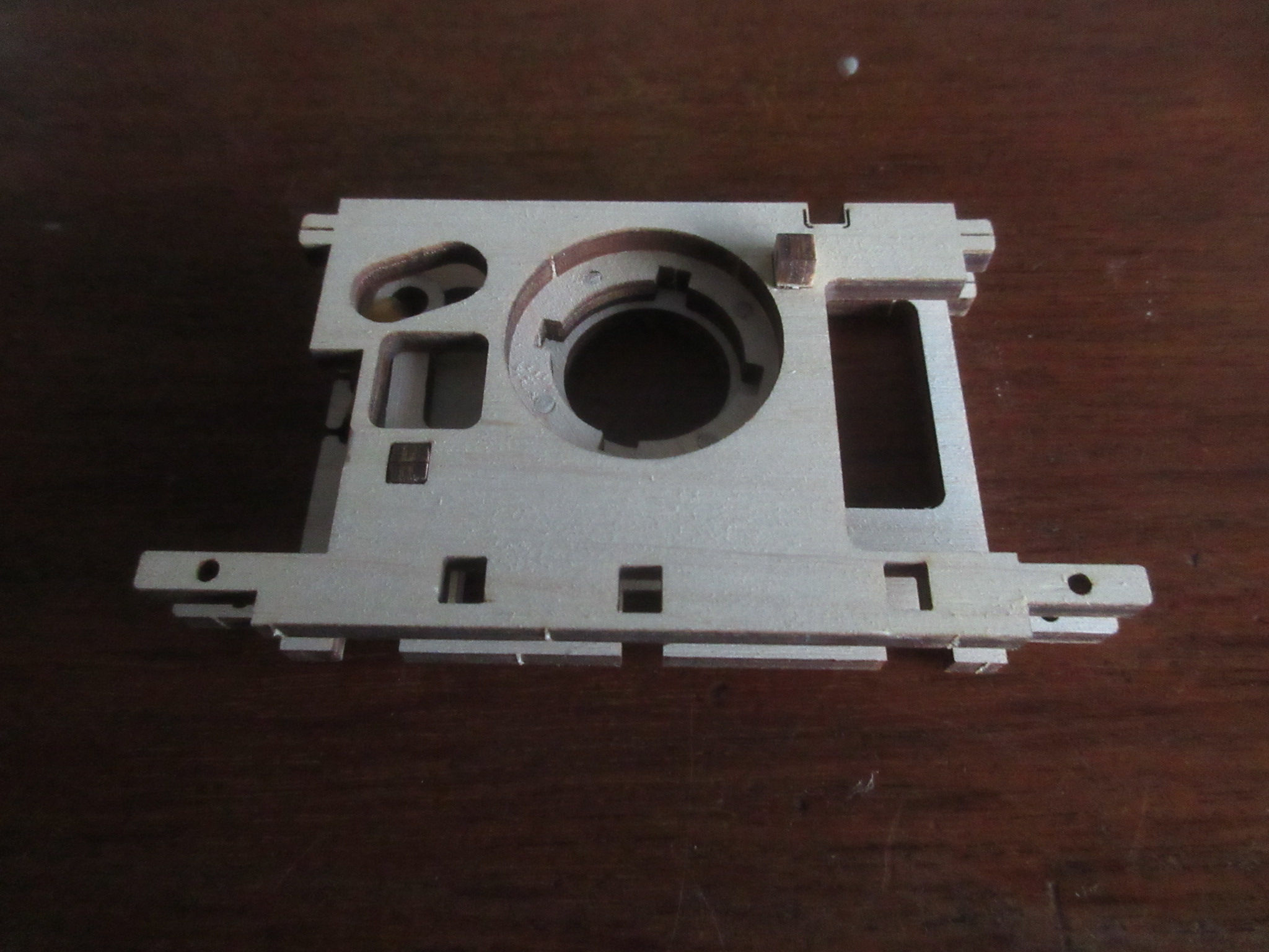
A Drive Shaft Bearing Plate ready to be added.
The Bearing Plate fitted.
Instruction Page 13.
More parts of the drive mechanism ready to be assembled.
The small circular parts are bearings so, along with the gear teeth, need to be carefully waxed before assembly. I found that waxing the ends of the shafts and any other pieces like the two short spacers will allow the parts to slip over the ends.
Care is needed during these assemblies as they cannot be fully tested until the build is past the point of no return.
Almost there.
The completed component.
Instruction Page 14.
Ready to attach the first Side Panel.
The assembled Gear Cog.
The Gear Cog sandwiched under its cover plate.
A Close Up showing the Cover Plate fixings and the Cog Bearing.
Instruction Page 15.
The Gearbox parts and Side Panel ready to put together.
The Gear unit ready to slide in through the side.
The assembled parts seen from above.
The completed assembly.
Seen from the right side.
Instruction Page 16.
Some components for one of the Gear Levers.
The Drivers Cabin Floor.
The second lever parts ready to go with the first assembly.
The completed Gear Lever assembly.
Seen from a different angle.
The Pivot pegs fitted to the floor pan.
The Gear Lever bearings seen from below.
And, seen from above.
Instruction Page 17.
An additional component to the gear lever mechanism.
The assembled component ready for fitting to the floor unit.
The component fitted to the two Pivot Pegs.
Instruction Page 18.
The 4 Gear Lever Cover support posts ready for fitting.
The Seat Base components.
The Support Pillars fitted.
The Gear Lever Cover will be fitted to these pillars later.
The completed Seat Bases.
The Seat Bases fitted to the floor pan.
It was at this point when the seats were fitted that I realised, with some disappointment, that I am building a Left Hand Drive car.
I will continue to the end and then assess if it would have been possible to reverse enough components to form a Right Hand Drive Version?
Instruction Page 19.
The assembled Floor Pan ready to fit into the Side Panel.
The Floor Pan fitted into the side panel.
Instruction Page 20.
The Drive Shaft Assembly. with Cog Teeth waxed.
Ready to fit under the Floor Pan.
The Drive Shaft and its Bearing Bracket fitted into the side wall.
Instruction Page 21.
The Rear Axle prepared for placing across the Gear Box.
The Rear Axle slotted into position.
The Right Side panel and Gear Wheel ready for fitting.
The Gear Wheel set on its spindle. The Cocktail stick is waxed to ease positioning.
The Cocktail Stick Peg is through the Spindle and then trimmed with the sharp knife.
Instruction Page 22.
The Right Side Panel ready for fitting.
The Right Side Fitted and pegged through the locating lugs.
The Engine Crankshaft with Bearings and Cams ready for assembling.
The Crankshaft assembled with bearings and cams waxed.
The Engine End Plates and Side Plates ready for fitting.
Wax the 4 Side Plate lugs for easier fitting.
The assembled Engine Sides with Speed Control plate parts ready for fitting.
Instruction Page 23.
The Speed Control plate fitted.
4 Pistons and Connecting Rods with their guide plate.
Both sets of Pistons assembled for this V8 Engine.
Both sets of Pistons and Cylinder Block plates.
Ready for fitting to the engine.
The assembled Cylinders.
The view from above.
The Top Cover parts and Drive Gears.
The Top Cover and Gear Wheels ready for fitting.
All fitted.
Instruction Page 24.
The upturned Engine and Support bracket.
Support Bracket fitted.
Speed Control Weights for assembly.
Speed Control Weights assembled.
Control Weights attached to the Support Plate
Instruction Page 25.
The Engine build so far, seen from below.
And, seen from the side and below.
The Speed Weight Balance Plate.
The assembled Balance Plate.
The Balance Plate attached to the Support Plate.
Instruction Page 26.
Double Gear Wheels to be attached to the Rear Engine Plate.
Spindle Pegs fitted through the Gear Wheels ready for fitting.
The Engine and Gear Wheels are ready to be fitted into the Chassis.
The Engine is attached to the Floor Pan via it Support Bracket.
The Chassis with Engine fitted and seen from above.
Instruction Page 27.
This little link rod is an additional part of the Speed Control mechanism.
These components form the first part of the Front Axle.
The Pegs, Bearings and Brackets actually form the front 'Sliding Pillar' suspension units.
The parts slotted together with waxed pegs at the ready.
The Fixing Pegs in place ready for trimming.
The 'Stub Axles' ready for attaching to their Pivot Brackets.
The Stub Axles attached and pegged.
That little Link Rod fitted to the Speed Control System.
The Link Rod from a different angle.
Instruction Page 28.
Waxed Bearings and Sliders for the Sliding Pillars at the top and Steering Tie Rod with waxed pegs below.
The assembled Sliding Pillars and Steering Track Tie Rod
The Sliding Pillar Top Bracket along with limiting collars and Cocktail Stick pegs.
The assembled and pegged unit with its top bracket used to fix it all to the car.
Instruction Page 29.
The Unit ready to fit to the car and two Suspension Spring Rubber Bands tied to the required length and trimmed.
Suspension Rubber Bands fitted under tension.
The Steering Unit fitted to the Engine Support Bracket along with its Top Bracket and with the Radiator.
The appearance of the Steering & Suspension from the front.
Instruction Page 30.
The parts needed to build the Radiator Grill.
The Base Plate and the Back Plate joined together. Remember to wax those joining tabs.
The carefully assembled Grill making sure not to mix up the slats.
Parts for the Engine Bay.
The sides are pegged together.
Trimmed and ready to fit.
The Radiator side tabs are waxed allowing the Side Walls to fit easily.
Instruction Page 31.
The Radiator, The Side Walls and the Headlamp Support Brackets, with pegs ready to fit to the body.
Parts fitted and pegs trimmed.
The lower front peg should not be trimmed and will have to be replaced later in the build once I discover this.
The first two parts of the five part Wheels assembled onto 5 half Cocktail Stick Pegs.
There are 5 of these wheels to prepare to this stage.
Instruction Page 32.
The Disc Brake, Spokes and Outer Rim parts making up the 5 for each wheel.
Note the wheel directional arrow on the outer rim. The Slotted Hubs are for the Rear Wheels. The Circular Hubs are for the two front wheels.
The assembled right rear wheel.
Three more ready to complete.
Two Front and Two Rear Wheels complete.
Trimmed and Peg Tops Sanded ready to fit to the Axles later.
Instruction Page 33.
Each Wheel has one larger spacer, two bearing spacers and a Cotter Pin outer fitment.
Four Wheels and Spacers fitted and the outer Cotter Pins slotted into their slots in the Axle Ends.
The Rear Trim Plate and Rear Bumper and trimmed to length pegs ready for fitting.
Both panel and bumper fitted with pegs ready to push until flush with the panel.
Two End Plates and Axles plus 16 Elastic Bands ready to assemble the Drive mechanism.
Eight Pairs of Bands are looped across the pegs to form an Octagon when viewing from one end.
The bands appear uneven in length but will even out when under tension and have been wound a few times.
Instruction Page 34.
The completed elastics and the winding ratchet parts, Gear Wheel and Bearing ready for fitting into the gearbox.
The ratchet Cog shows the 4 recesses ready for the 4 lugs on the elastic unit to slot into.
The two part Ratchet ready for peg trimming.
The assembled end ready for fitting with all teeth and bearing surfaces waxed.
Instruction Page 35.
The front end mechanism uses a disc with slots to take 6 small roller bearings to be covered by the large Cog.
The sides of both Disc & Cog, the Cog Teeth and the Roller Bearing all have to be waxed.
The rear end of the Elastic Motor is attached through the Spare Wheel and secured using another Cotter Pin.
The ratchet Cog clearly shows the 4 recesses with the 4 lugs on the elastic unit slotted into it. Both ends have to be slotted in the same.
Completed, The Spare Wheel is the winder for the elastic motor.
30 Half Turns required to fully wind.
The Assembly Build so far.
The Parts required to build the Scuttle and Dashboard.
Pinned ready for trimming and sanding.
It is worth waxing the the pegs for easier assembly.
The Scuttle has three support brackets for attaching the Dashboard.
The Steering Column has a Support Bracket with its bearing followed by 5 spacers and then another bearing which fits into the Dashboard followed by two more spacers and then the Steering Wheel.
Lastly there is one more bearing to fit onto the small lug in the front engine plate.
The completed Dashboard assembly.
The assembled Steering Column seen from the underside.
The Drivers Eye view.
Instruction Page 37.
The first Right Side Wing Panel with Pegs.
It was here that I realised that I should not have cut off the front peg earlier, so had to do some disassembly to re fit it before preceding.
The pegs have to be slotted into their recess before sliding on the 1st wing panel.
Wax the pegs to ease assembly.
The Scuttle slotted into place.
Again waxing the lugs will ease slotting in.
This shows both of the Steering Column bearings in place.
Instruction Page 38.
The rest of the left side wing panels set out in the correct sequence for fitting.
And, The Right Side Wing Panels.
The fitted Wings ready for trimming the pegs.
Instruction Page 39.
The parts for the Rear Toneau Cover, Overriders and Rear Lights.
The Gear Lever Slot with Hand Brake Lever.
The Rear Toneau fitted.
Here is a note of caution - DO NOT PRESS DOWN with the car standing on its wheels as I did.
The Three Ply used for all of the parts is not strong - My Rear Axle sheared close to the right side bearing.
Fortunately I managed to drill a 1mm hole in both parts of the broken shaft to fit a 1mm metal rod which was then araldited together and which seems to be holding.
For what it is worth saying, I had to make the same repair to the drive shaft on the first model I built.
The Gear Lever Slot and dummy Handbrake Lever fitted.
Assembling the Seat Backs.
The finished Seat Backs ready for fitting.
The fitted and complete Seats
Instruction Page 40.
The parts used to assemble the 4 Door Hinges.
The assembled Hinges and Door Panels.
The Hinges fitted to both Doors.
The Doors fitted to each pillar of the Scuttle Arch.
The first three parts used to form the Headlamps.
The first three parts of each lamp assembled.
Adding the last three parts to each Head Lamp.
The completed Head Lamps.
The parts used to assemble the Wing Top Side Lights.
Assembling the Side Lights.
Instruction Page 41.
The parts used for the Spot Lights.
The finished Spot Light.
The Headlamps, The Side Lights and the Spot Lamps fitted.
The Front Registration Plate and Overriders ready for fitting.
Number Plate & Overriders fitted.
Building the Bonnets is quite complex and it is important to keep each piece in sequence.
Take care not to break these small pieces.
The first 4 pieces of the Right Side Bonnet assembled including the Hinge Piece, with 2 support brackets ready to fit.
Support Brackets fitted.
Instruction Page 42.
The next 6 parts ready to be added in numerical sequence.
Parts Fitted, with the left side holes forming the Louvers.
Seen from inside.
The next 8 Bonnet Ribs plus an additional Support Bracket.
Parts fitted. Seen from inside.
Instruction Page 43.
The last 7 pieces including the front Hinge Piece and two pegs.
The completed Bonnet seen from inside.
The finished bonnet temporary fitted to the car, and ready to have its pegs trimmed.
Instruction Page 44.
The completed Left Side Bonnet from inside.
The left side Bonnet ready for fitting to the car.
Instruction Page 45.
The Bonnets joined with Two Locating Pegs.
Seen from inside once more.
The Bonnets fitted and presented in Wings Up format.
The Bonnet Hinge Pegs trimmed and located into its securing holes.
Instruction Page 46.
The car, ready to have its Windscreen, Wing Mirrors and Bonnet Top fitted.
Completed at last.
Right Side View
Left or Drivers Side view.
The Controls
Instruction Page 47.
The Gearbox
Forward Drive - Neutral - Reverse
Footnote.
As I write, it is good that the car runs and has reasonable traction.
However, I now needed to do a full diagnostic on the Gearbox.
The car originally would run when the gear lever was in Forward, Reverse and in Neutral as well, but all in the reverse direction.
However on close inspection it appeared that one of the sliding levers in the gearbox was not located under its counter part. A simple fix and all works well now.


